Aircraft Floor Beam Shear Diagram

Bending Moment And Shear Force Diagram For Overhanging Beam In 2020 Bending Moment Shear Force Structural Analysis

Shear And Moment Diagrams Structural Analysis In This Moment Structural Engineering

Pin Em Ingenieria Mecanica Y Electronica

Typical Beam Diagrams Deflection Shear And Bending Diagrams Structural Analysis Civil Engineering Construction Civil Engineering Design

Shear In Bending

Pin On Beam

5 integrated aircraft floor with longitudinal beams.
Aircraft floor beam shear diagram.

Significance Of Shear Force Diagram And Bending Moment Diagram Shear Force Structural Engineering Structural Analysis
Definition Of Shear And Moment Diagrams Chegg Com

Get Answer Draw The Shear Diagram For The Beam Begin By Placing Vertical Transtutors

Beam Design With Mathcad Beam Fixed At Both Ends Uniformly Distribut Beams Design In This Moment

Shear Force And Bending Moment Diagram For Fixed Beam With Udl In 2020 Bending Moment Shear Force Beams
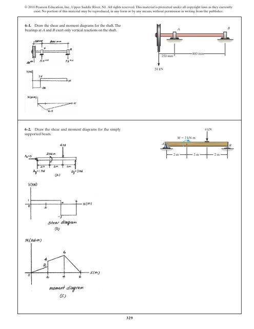
329 6 1 Draw The Shear And Moment Diagrams For Aerostudents

Pin Na Nastence Kovarstvi

Shear Force And Bending Moment Diagram Of Continuous Beam In 2020 Bending Moment Shear Force In This Moment

Beam And Column Layout Plan How To Plan Column Layout

Learn Shear Force Bending Moment Online Problem On Sfd Bmd Bending Moment Shear Force In This Moment

Rcc Cantilever Beam Reinforcement Details Structural Engineering Concrete Design Concrete Architecture

Some Useful Tips To Study The Drawing Of Plinth Beam In Construction Site Structural Drawing Construction Estimating Software Plinths

Solved Draw The Shear Diagram For The Beam Follow The Sign 1 Answer Transtutors
Solved Problem 7 85 Part A Draw The Shear Diagram For The Beam Part 1 Answer Transtutors

Pin On Beam

Shear And Moment Diagram Shear Force Portal Frame Bending Moment Bending Moment Angle Plan Shear Stress Png Pngwing

So Much Detail Aircraft Design Vickers Vc10 Aircraft

Structural Analysis And Design Of Residential Buildings Using Manual Calculations According To Eurocode 2 Engineering Basic Structural Analysis Residential Building Civil Engineering Design
Https Encrypted Tbn0 Gstatic Com Images Q Tbn 3aand9gcqbdyse0l Itxlctwatylj0noenctmxdxutkf7ujo4 Ry9dlweh Usqp Cau

Steel Beam Calculator Excel Metric In 2020 Beams Steel Beams Structural Analysis

Un Reinforced Masonry Wall Collapse In Out Of Plane Motion Due To Lack Of Integrity And Stability Masonry Wall Masonry Wall

Double Span Portal Frame Beam Column Haunch Valley Connection Frame Design Roof Beam Building Information Modeling


Shear And Moment Diagrams S B A Invent Civil Engineering Books In This Moment Engineering Science
Source : pinterest.com
